
Yamaha rattled a few cages when it announced its partnership with accessory king RAM Mounts for its entire 2019 FX WaveRunner lineup. Replacing the screw-top watertight storage cubby on previous models, the new FX’s feature a pair of Hydro-Turf padded recesses where either a cup holder or a sturdy triangular puck can be mounted. The puck is cast with a slight recess permitting a small wireloom to feed through. This was intentionally made to permit a Garmin or other handheld-style GPS to be mounted.
Through Yamaha’s newly expanded accessory catalog, customers could opt for the Garmin GPS and transducer package (a standard feature on the top-of-the-line Yamaha FX Limited SVHO WaveRunner). The transducer is non-invasively mounted externally, sharing the existing bolt holes with the ski’s folding swim step bracket. Yet, for those adventurers looking to truly explore new and exotic locations far beyond the constraints of a single-tank of fuel, often require more in the way of superior navigational equipment.
Top left: First, remove the push pins holding the 2-piece bulkhead wall from the front storage bin. Top right: Remove the 3 bolts holding the decorative trim from the righthand side. Bottom left: One of the 3 requires a 10mm socket. Bottom right: All others require the same 4mm hex driver.
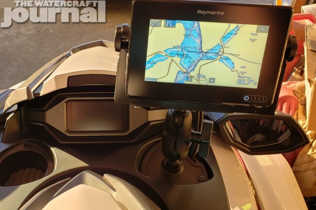
Recently, The Watercraft Journal spoke with Middle Tennessee Personal Watercraft Club member Tom Hill, who walked us through how he installed a Raymarine Axiom 7 Chartplotter and DownVision through-hull transducer. Hill chose the Axiom not only for its compatibility with other Raymarine accessories, but also its Wi-Fi and Bluetooth connectivity, multifunction navigation system, RealVision 3D sonar, and detailed DownVision sonar.
First, disconnect the battery (positive and negative) after removing the split bench seat. Next, remove the bulkhead partition between the front cargo bin and engine compartment (it separates into two plastic pieces). They each have two white plastic push pins that you will need to push the very center pin in. A small Phillips screwdriver will help push them in then remove whole pin. Once the pins are removed you can separate the two pieces for removal by sliding them towards each other to unlock the center section.
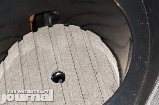
Top left: The fairing running alongside the console slides out. Don’t pull it off or you’ll break the tabs. Top right: The through-hull transducer is set back in the rear of the hull, pressed into a thick bead of pure clear silicone and left to cure over 24 hours. Bottom left: The factory cupholders come with a relief to let wires through. Bottom right: We had to open up the hole to let the larger Raymarine plugs through.
Remove the side trim panel that would be on the inside of your right leg when sitting on ski. There are three 4mm hex bolts. There is one nut hidden in the engine compartment that a requires a 10mm socket. With these removed, you can remove the large fairing running alongside the console (on the right-hand side) via the same 4mm hex socket. There are three hex socket bolts. Gently slide it forward so the tabs that go into the center console unhook.
With these removed, you now have full access to everything you need. Hill mounted his DownVision transducer in the right rear of the hull, pressing it into a bead of 3M pure silicone squeezed from a caulk tube. Hill notes that the object here is to avoid any air bubbles in the silicone. He explains, “I put down about 3/4-inch thick bead and kinda push and slightly turn the transducer back and forth to squish out most of the silicone. That way you get no air pockets underneath it.” Let it dry 24 hours before proceeding.
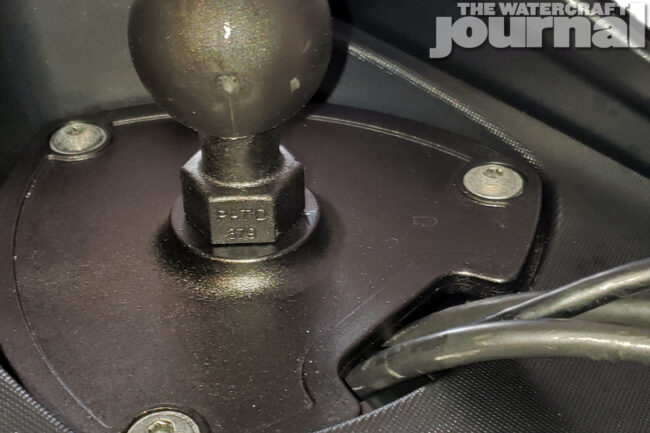
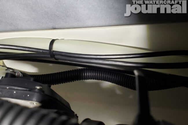
Top left: Once we ran all of our GPS’ wires through, we reused the factory rubber boot and tie to close up the opening. Top right: We installed the factory RAM mount puck using the 3 hex bolts with a larger RAM ball socket. Bottom left: Because of the heft of the 7-inch Raymarine GPS, we went with the larger diameter mount and coupler. Bottom right: And now, we can install our Raymarine chartplotter.
Once the silicone has dried, run the wires up from transducer on the right side of engine and lay them on the fuel tank. (Make sure to also run power lines to the battery, but do not connect them to battery yet.) With the wires resting on the tank, you can reach them from the front hatch area. Take a flashlight and look up under the hatch. There you will see a rubber boot coming down from the console near the steering mechanism where the factory wiring and the steering cable runs through it. There is a removable cable tie on it.
Simply remove the cable tie (to be reused later) and feed the power and transducer cables up through the boot. Smartly, the cup holder has a small hole in the base where the cables can be fed through.Unfortunately, the Raymarine Axiom 7 cable ends are just larger than the hole, so we used a round file to make the hole a little larger. Now fasten the factory supplied accessory mount on via three 4mm hex socket bolts.
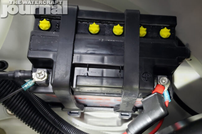
Top left: We ran our wire loom parallel with the factory footwell drain hoses and ziptied the two together. Top right: With our wiring complete, we finally attached our harness to the battery. Bottom left: Now we can backtrack our steps and reinstall our fairing and trim panels. Bottom right: Now we’re ready to hit the water and chart a new course through some new, unfamiliar areas!
The Axiom 7 is fairly heavy compared to other smaller GPS units, so we used a RAM mount size-C ball with 1/4-inch by 20 stud. The thread on the factory mount plate is 1/4 x 20 and a 1/2-inch deep (the hole does not go all the way through). The RAM ball stud was too long for the mount so we had to cut it shorter. Once done, we used a little blue Loctite on the shortened ball stud. We also purchased RAM Mount 3.5-inch marine aluminum extension and the appropriate base holder for the chart plotter.
Once hard mounted, we were ready to connect the wires to the battery. We do recommend an inline fuse on the positive side. Once we finalized our installation we zip-tied our new wires to the drain hose running down the side of the ski for a neat and tidy layout. You don’t want wires flopping around when you hit the rough stuff. Finally, we reinstalled the panels back on (following our steps in reverse order) and off we went.
Special thanks to Tom Hill and providing The Watercraft Journal the text and copy.









[…] up as many miles as possible, we turned to Tom Hill, who many will remember from our tutorial on installing a Raymarine Axiom 7 Chartplotter and Transducer on a ’19 Yamaha FX […]